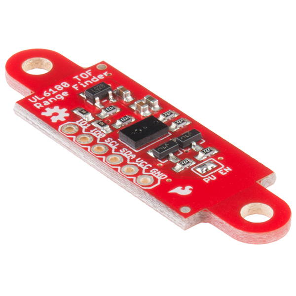
SparkFun ToF Range Finder Sensor - VL6180
Key Features Measures absolute range up to 10cm Gesture Recognition 3-in-1 Module: IR Emitter, Range Sensor, Ambient Light Sensor Two Programmable GPIO Sharp Sensor Board Layout The EasyDriver is a simple to use stepper motor driver, compatible with anything that can output a digital 0 to 5V pulse (or 0 to 3.3V pulse if you solder SJ2 closed on the EasyDriver). The EasyDriver requires a 6V to 30V supply to power the motor and can power any voltage of stepper motor. The EasyDriver has an on board voltage regulator for the digital interface that can be set to 5V or 3.3V. Connect a 4-wire stepper motor and a microcontroller and you & #39; ve got precision motor control! EasyDriver drives bi-polar motors, and motors wired as bi-polar. I. e. 4, 6, or 8 wire stepper motors. This EasyDriver V 4.5 has been co-designed with Brian Schmalz. It provides much more flexibility and control over your stepper motor, when compared to older versions. The microstep select (MS1 and MS2) pins of the A3967 are broken out allowing adjustments to the microstepping resolution. The sleep and enable pins are also broken out for further control. Item Specifics 2.8V Regulator - Provides the required 2.8V for the sensor I2C Level Shifter - Provides logic level conversion from 2.8V to VCC I2C Interface Basic soldering skills required Competent programming skills required Some electrical prototyping skills required
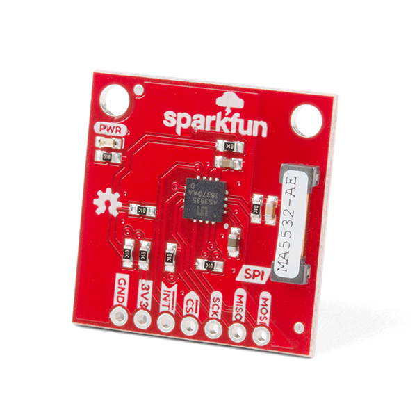
SparkFun Lightning Detector - AS3935 Add Lightning detection to your weather station Programmable detection level Distance to storm estimator Indoor-O
The SparkFun Lightning Detector adds lightning detection to your next weather station to make sure you are aware of any potential hazardous weather heading your way. The AS3935 is capable of detecting lightning up to 40km away with an accuracy of 1km to the storm front with a sensitive antenna tuned to pick up lightning events in the 500kHz band.There are a number of sources that can cause false positives but the lightning detector itself can reliably filter these out by default. If not, we've made sure to include settings you can configure using the lightning detector library to increase the chip's robustness to noise and false positives. The lightning detector library also gives you access to settings such as storm sensing sensitivity when detecting indoors vs outdoors, or the number of lightning strikes needed to trigger an interrupt.Lightning Sensing40km Range with accuracy of 1km in 14 stepsFeaturesProgrammable Detection LevelsDistance to storm estimation"Disturber" (false event) rejection algorithmIndoor and Outdoor SettingsSPI InterfaceOperating RangeSupply Voltage: 2.4V - 5.5V
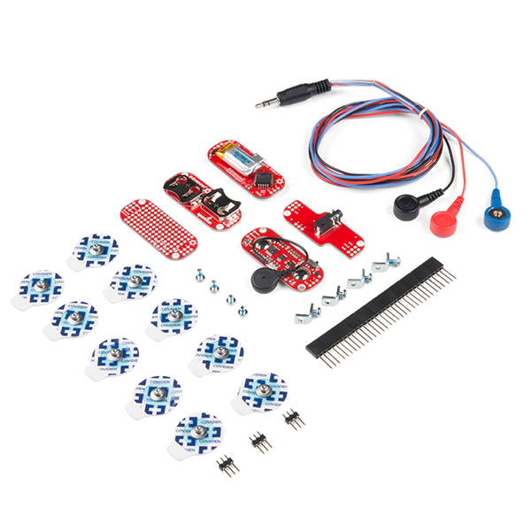
SparkFun MyoWare Muscle Sensor Development Kit
Key Features Arduino-powered, electromyography (EMG) sensor kit MyoWare board measures the filtered and rectified electrical activity of a muscle It & #39; s very simple to hook up this kit Everything you need is in the kit - battery included Using our muscles to control things is the way that most of us are accustomed to doing it. We push buttons, pull levers, move joysticks... but what if we could take the buttons, levers and joysticks out of the equation? This is the MyoWare Muscle Sensor Development Kit, an Arduino-powered, electromyography (EMG) sensor kit that provides you with a MyoWare Muscle Sensor, each MyoWare shield, and everything you need to connect them all together. The MyoWare board included in this kit acts by measuring the filtered and rectified electrical activity of a muscle; outputting 0-Vs Volts depending on the amount of activity in the selected muscle, where Vs signifies the voltage of the power source. It & #39; s very simple to hook up this kit, attach shields to the muscle sensor, stick on a few included electrodes, read the voltage out and flex some muscles! Note: The Power Shield and the LED Shield both provide power, but at slightly different voltages. Don & #39; t use both of these shields at the same time. Item Specifics 1 - MyoWare Muscle Sensor 1 -MyoWare Power Shield 1 - MyoWare Cable Shield 1 - MyoWare LED Shield 1 - MyoWare Proto Shield 1 - Sensor Cable --- 3 Connector 10 - Biomedical Sensor Pad 11 - Stackable Header --- 3 Pin, Female 3 - Header --- 3 Pin, Male
FTDI Cable 5V VCC-3.3V I/O
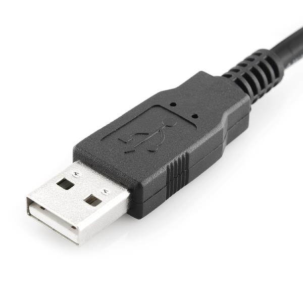
Description: The FTDI cable is a USB to Serial (TTL level) converter which allows for a simple way to connect TTL interface devices to USB. The VCC pins of this FTDI cable are configured to operate at 5V with 3.3V I/O.The FTDI cable is designed around an FT232RQ, which is housed in a USB A connector. The other side of the cable is terminated with a 0.1" pitch, 6-pin connector with the following pinout: RTS, RX, TX, 5V, CTS, GND (RTS is the green cable and GND is black).This cable has almost the same pinout and functionality as our FTDI Basic Breakout board; you can use it to program your Arduino Pro, Pro Mini and Lilypad, etc. For use with those boards, align the black and green wires of the FTDI cable with the 'BLK' and 'GRN' labels on the PCB. The difference between this cable and the FTDI Basic Breakout is the cable has a 5V Vcc where as the breakout has a 3.3V Vcc. You will still be able to program an Aruidno Pro, Pro Mini, Lilypad, etc. The 5V Vcc supply will not damage these Arduino circuit boards.These have 5V VCC, and 3.3V I/O. The 5V Vcc output shouldn't be a problem unless this cable is being used to power a sensitive circuit such as a sensor.There are pros and cons to the FTDI Cable vs the FTDI Basic. The FTDI Basic has great LED indicators, but requires a Mini-B cable. The FTDI Cable is well protected against the elements, but is large and cannot be embedded into a project as easily. The FTDI Basic uses DTR to cause a hardware reset where the FTDI cable uses the RTS signal.
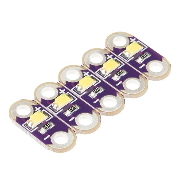
SparkFun Lilypad LED White (5 LEDs)
Key Features: 5 pack of white LEDs Snap-a-part design lets you choose how many to use Designed to be sewn onto fabric Wearable e-textile tech that is washable This is a simple pack of five White LilyPad LEDs that are still attached to one another, letting you snap the LEDs apart at your leisure to sew into clothing or whatever else you can dream up. LilyPad is a wearable e-textile technology developed by Dr. Leah Buechley and cooperatively designed by Leah and SparkFun. Each LilyPad piece was creatively designed with large sew tabs to allow them to be sewn into fabric. Various input, output, power and sensor boards are available. They & apos; re even washable (with special care)! Item Specifics 5 - LEDs Color: White Size: 5.5 mm x 12.5 mm Thin 0.8 mm PCB
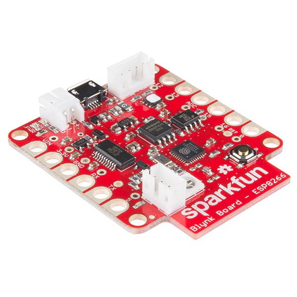
SparkFun Blynk Board - ESP8266
Key Features: Easy to use app builder; drag and drop widgets Add a variety of buttons, sliders, graphical displays and even RGB controllers to your phone Control the Blynk board or any other compatible hardware remotely by displaying sensor data, analyzing your surroundings, activating a function of your project and much more Comes with Blynk app subscription The SparkFun Blynk Board is specially designed to work with the ‘widgets’ within the Blynk mobile app to create your next IoT project. Monitor local weather conditions, control LEDs from your phone, even send a tweet when it’s time to water your plants! Every Blynk Board comes fully programmed and also includes a Blynk subscription code card (15k Energy at a $10 value), which will be needed to connect the Blynk Board to your Blynk account, connect to a Wi-Fi signal and you are ready to start Blynking! The onboard ESP8266 framework allows you to connect to most 2.4GH z WiFi networks (open or password protected). The Blynk Board input/ouput (I/O) pins can either control motors or LEDs, or read in values from light & position sensors. Each of the pins are located on the edge of the board and interface with alligator clip cables – a staple interface cable for beginner and advanced electrical engineer alike. Multi-colored LEDs indicate all sorts of status modes including how to identify which board is yours. Item Specifics ESP8266-Based On-Board Si7021 Temp/Humidity sensor Solderless pin connectors - compatible with alligator clips On-Board FTDI for re-programming On-board WS2812 RGB LED General purpose LED and button ADC scaled to 0- 3.3V Expansion connectors for I2C and WS2812 output LiPo battery charger Arduino programmable No programming required to connect the board to Blynk and run through the example projects Blynk Subscription Code-Card Included
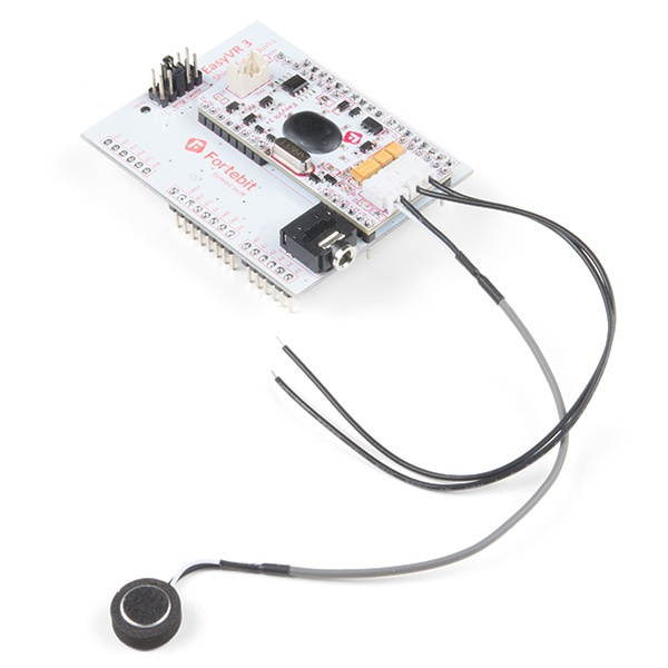
SparkFun EasyVR 3 Plus Shield (Arduino Compatible)
Key Features: A selection of 26 built-in Speaker Independent (SI) commands for ready-to-run basic controls in 6 languages Up to around 21 minutes of pre-recorded sounds or speech Up to about 137 seconds of live message recording and playback Real-time Lip-sync capability Do you make time to talk to your Arduino? Maybe you should! The EasyVR 3 Plus Shield is a voice recognition shield for Arduino boards integrating an EasyVR module. This kit includes the EasyVR 3 Plus Module, the Arduino Shield Adapter, microphone, and headers. With all of these parts, everything has been provided to you to get up and running in a short amount of time with minimal soldering! EasyVR 3 Plus is a multi-purpose speech recognition module designed to add versatile, robust and cost effective speech recognition capabilities to almost any application. The EasyVR 3 Plus module can be used with any host with a UART interface powered at 3.3V & ndash; 5V, such as PIC and Arduino boards. Some application examples include home automation, such as voice-controlled light switches, locks, curtains or kitchen appliances, or adding & ldquo; hearing & rdquo; to the most popular robots on the market. Item Specifics 1 - EasyVR 3 Plus Module 1 - EasyVR Shield 3 1 - Wired Microphone 1 - Speaker cable (Speaker not included) 1 - Header Set Does not come pre-assembled Some soldering and assembly required before operation
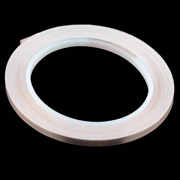
SparkFun Copper Tape Roll - 5mm x 50ft
Key Features: Non-conductive adhesive-backed 5mm wide and comes in rolls of 50ft Thickness: 3 mil Copper tape has countless applications in electronics from creating low-profile traces for electrical components to RF-shielding and antenna-making. Copper tape is even used to join things together using solder, like the stained glass on Tiffany lamps. The 5mm copper tape is a great option for making paper circuit traces. It & apos; s a better option compared to using the 2" copper tape. Item Specifics Length: 50 & apos; Width: 5mm Thickness: 3mil This raw copper is not coated and can build up a layer of verdigris over time unless it is sealed. The adhesive on this copper tape is not conductive
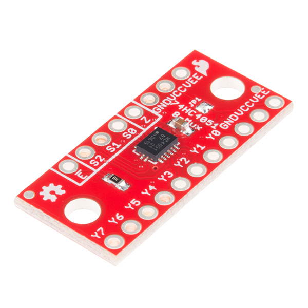
SparkFun Multiplexer Breakout - 8 Channel (74HC4051)
Key Features Switches analog or digital signals 8 channels controlled by 3 select inputs Access to all pins and features of a 8-channel analog multiplexer/demultiplexer (74HC4051) Turn four I/O pins into eight multifunctional, individually selectable signals The SparkFun Multiplexer Breakout provides access to all pins and features of the 74HC4051, an 8-channel analog multiplexer/demultiplexer. The 74HC4051 allows you to turn four I/O pins into eight multifunctional, individually selectable signals, which can be used to do everything from driving eight LEDs to monitoring eight potentiometers. The 74HC4051 can function as either a multiplexer or a demultiplexer, and it features eight channels of selectable inputs/outputs. The routing of common signal to independent I/O is set by digitally controlling three select lines, which can be set either high or low into one of eight binary combinations. One half of the board breaks out the control signals (E, S0-S2) and common input/output (Z). The other side provides access to all eight independent I/O & rsquo; s (Y0-Y7). Both sides include supply and ground connections (VCC, VEE, GND) Item Specifics Wide voltage supply range: 2 -- 10V Bipolar supply support (e. g., & plusmn; 5V) Optional enable input Breadboard compatible breakout
SparkFun Lilypad LED Green (5 LEDs)
Key Features Simple pack of five Green LilyPad LEDs Sew into clothing or whatever else you can dream up Designed with large sew tabs to allow them to be sewn into fabric Washable (with special care) This is a simple pack of five Green LilyPad LEDs that are still attached to one another, letting you snap the LEDs apart at your leisure to sew into clothing or whatever else you can dream up. LilyPad is a wearable e-textile technology developed by Dr. Leah Buechley and cooperatively designed by Leah and SparkFun. Each LilyPad piece was creatively designed with large sew tabs to allow them to be sewn into fabric. Various input, output, power and sensor boards are available. They & #39; re even washable (with special care)! Item Specifics Size: 5.5 mm x 12.5 mm Thin 0.8 mm PCB

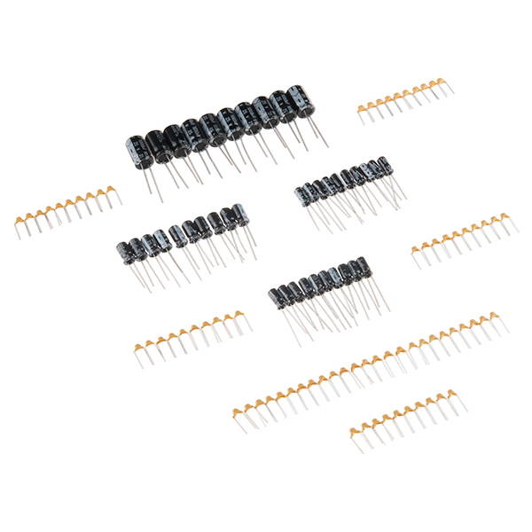
SparkFun Capacitor Kit
Key Features Basic assortment of capacitors Over 100 of the most popular capacitors Comes in a box with each capacitor identified Great gift for beginner and advanced electronics enthusiasts This is a kit that provides you with a basic assortment of capacitors to start or continue your electronics tinkering. No more looking under your desk to see if you can find a spare capacitor you might have dropped a year ago. With this kit you get over 100 of the most popular capacitors. As a bonus they come in a box with a sticker to help you identify which capacitor is which. This assortment of capacitors makes a great gift for beginner and advanced electronics nerds at any time of year! Item Specific 10 - 10pF capacitors 10 - 22pF capacitors 10 - 100pF capacitors 10 - 1nF capacitors 10 - 10nF capacitors 25 - 100nF capacitors 10 - 1 & micro; F capacitors 10 - 10 & micro; F capacitor 10 - 100 & micro; F capacitors 10 - 1000 & micro; F capacitors
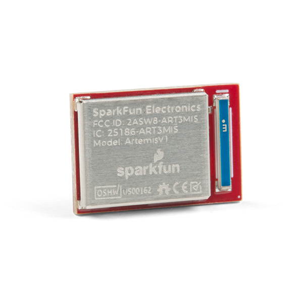
SparkFun Artemis Module-Low Power Machine Learning BLE Cortex-M4F Powered by the Apollo3 chip TensorFlow compatible Easy to use Time to first blink in
The Artemis Module from SparkFun is a Cortex-M4F with BLE 5.0 running up to 96MHz and with as low power as 6uA per MHz (less than 5mW). This is the world's first module to bridge the market between hobbyists and consumer products. We've packaged all the power of a modern microcontroller into a module that is both extremely easy to use but is mass-market ready.The flexibility of the Artemis module starts with our Arduino core. You can program and use the Artemis module just like you would an Uno or any other Arduino. Time to first blink is just 5 minutes away! We built the core from the ground up, making it fast and as light weight as possible.Next is the module itself. Measuring 10x15mm the Artemis module has all the support circuitry you need to use the fantastic Apollo3 processor in your next project. We're proud to say the SparkFun Artemis module is the first open source hardware module with the design files freely and easily available. We've carefully designed the module so that implementing Artemis into your design can be done with low-cost 2-layer PCBs and 8mil trace/space.Made in the USA at SparkFun's Boulder production line, the Artemis module is designed for consumer grade products. This truly differentiates the Artemis from its Arduino brethren. Ready to scale your product? The Artemis will grow with you beyond the Uno footprint and Arduino IDE. Additionally, the Artemis has an advanced HAL (hardware abstraction layer) allowing users to push the modern Cortex-M4F architecture to its limit.The SparkFun Artemis Module is fully FCC/IC/CE certified and is available in full tape and reel quantities. With 1M flash and 384k RAM you'll have plenty of room for your code. The Artemis module runs at 48MHz with a 96MHz turbo mode available and with Bluetooth to boot!Be sure to checkout the various carrier boards we've assembled to make exploring the Artemis extremely easy. We encourage you to start from our designs and design the next amazing product!
SparkFun Tiny AVR Programmer
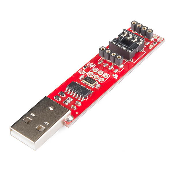
Key Features Plugs directly into your USB port and provides a programming socket for the ATTiny45 and 85 Shrink your Arduino projects down to "tiny size" No need for breadboards, jumper wires or a hardware programmer Easily prototype around the ATtiny without pulling and plugging it over and over. The ATtiny45 and 85 are a couple of really cool little MCUs but did you know you can program them in Arduino? That & #39; s right, now you can shrink your Arduino projects down to "tiny size" by moving your code straight over to these small but capable ICs. The standard method for programming the ATtiny ICs involves a breadboard, lots of jumper wires and a hardware programmer, but David Mellis over at MIT Media Lab has simplified the process by laying out this handy USB programmer. The Tiny AVR Programmer plugs directly into your USB port and provides a programming socket for the ATTiny45 and 85. Just slot an ATtiny with a DIP footprint into the socket, plug the programmer into your USB port and start up the Arduino IDE. After installing the proper board definitions, you simply program it the same way you would any other Arduino board. The programmer even breaks out the IC pins to female headers so you can easily prototype around the ATtiny without pulling and plugging it over and over. There are two ISP headers that have also been broken out so you can use the programmer or solder in a 6-pin header for other AVR microcontrollers! Item Specifics Basic soldering skills required Fundamental programming skills required Basic electrical prototyping skills required Note: You & #39; ll need to install the USB TinyISP drivers if you don & #39; t have them yet.
SparkFun Soil Moisture Sensor (with Screw Terminals)
Key Features Simple breakout for measuring the moisture in soil Includes a 3-pin screw pin terminal pre-soldered to the board for easy wiring and setup PCB coated in gold finishing ( Electroless Nickel Immersion Gold) The SparkFun Soil Moisture Sensor is a simple breakout for measuring the moisture in soil and similar materials. The soil moisture sensor is pretty straightforward to use. The two large, exposed pads function as probes for the sensor, together acting as a variable resistor. The more water that is in the soil means the better the conductivity between the pads will be, resulting in a lower resistance and a higher SIG out. This version of the Soil Moisture Sensor includes a 3-pin screw pin terminal pre-soldered to the board for easy wiring and setup. To get the SparkFun Soil Moisture Sensor functioning, all you will need is to connect the VCC and GND pins to your Arduino-based device (or compatible development board). You will receive a SIG out, which will depend on the amount of water in the soil. One commonly known issue with soil moisture senors is their short lifespan when exposed to a moist environment. To combat this, we & rsquo; ve had the PCB coated in gold finishing (ENIG, or Electroless Nickel Immersion Gold). Item Specific Fundamental programming skills required

SparkFun Beefy 3 - FTDI Basic Breakout
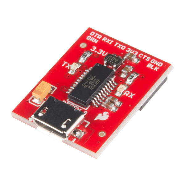
Key Features Pinout of this board matches the FTDI cable to work with official Arduino and cloned 3.3V Arduino boards Built upon the same foundation as our 3.3V SparkFun FTDI Basic Breakout, the Beefy 3 is equipped with an AP2112K voltage regulator Able to power a 3.3V project directly from the FTDI Designed to decrease the cost of Arduino development and increase ease of use This is SparkFun Beefy 3 FTDI Basic Breakout for the FTDI FT231X USB to serial IC. The pinout of this board matches the FTDI cable to work with official Arduino and cloned 3.3V Arduino boards. It can also be used for general serial applications. This board brings out the DTR pin as opposed to the RTS pin of the FTDI cable. The DTR pin allows an Arduino target to auto-reset when a new Sketch is downloaded. This is a really nice feature to have and allows a sketch to be downloaded without having to hit the reset button. This board will auto reset any Arduino board that has the reset pin brought out to a 6-pin connector. The pins labeled BLK and GRN correspond to the colored wires on the FTDI cable. The black wire on the FTDI cable is GND, green is DTR. Use these BLK and GRN pins to align the FTDI basic board with your Arduino target. There are pros and cons to the FTDI Cable vs the FTDI Basic. This board has TX and RX LEDs that allow you to actually see serial traffic on the LEDs to verify if the board is working, however this board now requires a Micro-B USB cable. The FTDI Cable is well protected against the elements, but is large and cannot be embedded into a project as easily. The FTDI Basic uses DTR to cause a hardware reset where the FTDI cable uses the RTS signal. Item Specific Max current load: 600mA Basic soldering skills required
sparkfun big easy driver stepper motor driver board for bi-polar stepper motors up to a max 2a/phase maximum motor drive voltag
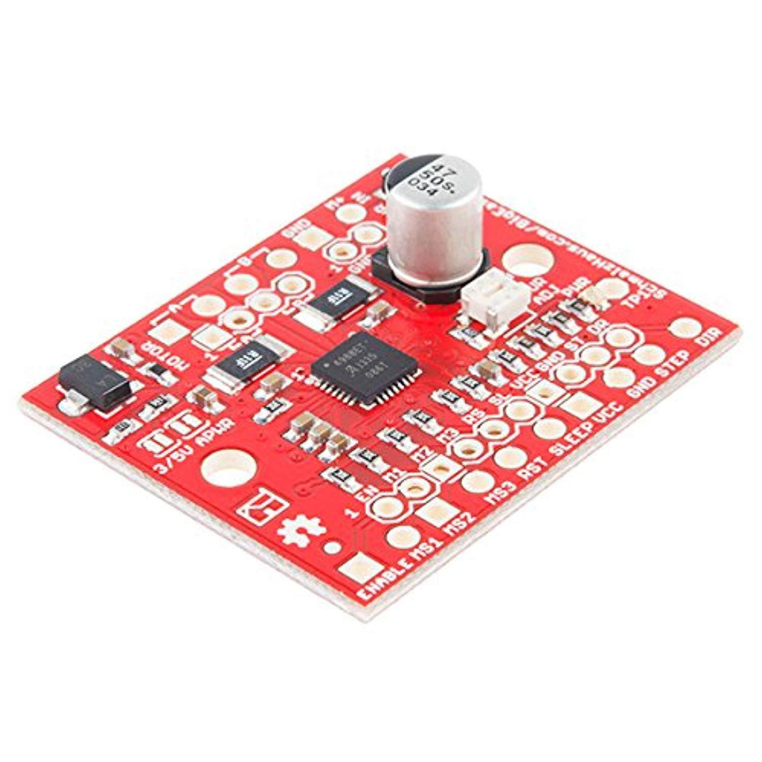
sparkfun big easy driver stepper motor driver board for bi-polar stepper motors up to a max 2a/phase maximum motor drive voltage of around 30v includes on-board 5v/3.3v regulation allegro a4988 chipThe Big Easy Driver, designed by Brian Schmalz, is a stepper motor driver board for bi-polar stepper motors up to a max 2A/phase. It is based on the Allegro A4988 stepper driver chip. It's the next version of the popular Easy Driver board.Each Big Easy Driver can drive up to a max of 2A per phase of a bi-polar stepper motor. It is a chopper microstepping driver which defaults to 16 step microstepping mode. It can take a maximum motor drive voltage of around 30V, and includes on-board 5V/3.3V regulation, so only one supply is necessary. Although this board should be able to run most systems without active cooling while operating at 1.4-1.7A/phase, a heatsink is required for loads approaching 2A/phase. You can find the recommended heatsink in the related items below.Features:Bi-polar Microstepping Driver2A/Phase Max1.4-1.7A/Phase w/o HeatsinkMax Motor Drive Voltage: 30VOn-board 5V/3.3V Regulation
SparkFun Tsunami Super WAV Trigger
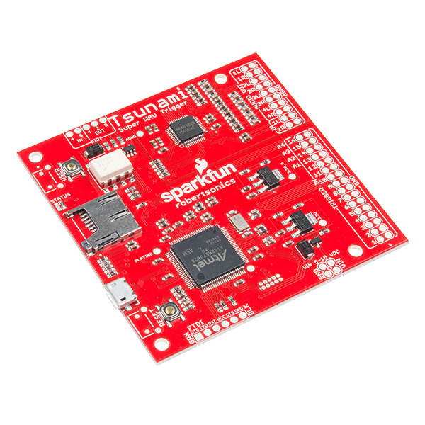
Key Features Supports up to 4096 uncompressed 16-bit, 44.1 kHz mono or stereo WAV files Polyphonic & ndash; Play and mix 32 mono or 18 stereo tracks independently and simultaneously Trigger inputs can be individually inverted Seamless looping over arbitrary track length Based on a new generation ARM Cortex M7, the Tsunami extends polyphony to 32 mono or 18 stereo simultaneous uncompressed 44.1 kHz, 16-bit tracks. Each track can start, pause, resume, loop and stop independently, and can have its own volume setting, allowing you to create the perfect interactive mix of music, dialog and sound effects. It supports true seamless looping over an arbitrary track length. The big news is that the Tsunami has 8 audio output channels, arranged as either 8 mono or 4 stereo pairs. The mono version adds a new & ldquo; Synced Set & rdquo; trigger function that can start up to 8 mono tracks on adjacent outputs. These tracks will start and stay in sample-sync for playing stereo or even 5.1 or 7.1 surround sound content with a single trigger. Any track can be dynamically routed to any output. And each output provides independent real-time volume and sample-rate conversion (pitch bend). Each Tsunami Super WAV Trigger has a dedicated MIDI port with an integrated opto-isolator, making it easy to connect to any MIDI controller. Tsunami & rsquo; s MIDI implementation includes control of volume, pitch bend, attack and release times, and the ability to route any MIDI key to any of the output channels, as well as specifying single-shot or looping playback per key. Item Specifics Triggers and serial RX are not 5V tolerant Trigger-to-sound delay: 8 msecs typ, 12 msecs max Outputs provide independent real-time playback rate control and MIDI Pitch Bend/ Output volumes adjustable from +10dB to -70dB/ Firmware track fades (attacks & decays) A dedicated & ldquo; Play & rdquo; status digital output pin
SparkFun Micro OLED Breakout (Qwiic)
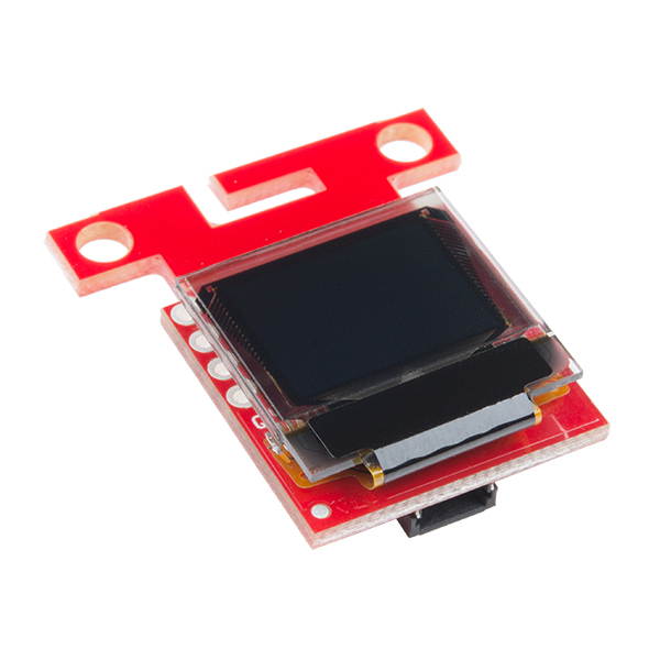
Key Features Screen Size: 64x48 pixels ( 0.66" Across) Small monochrome, blue-on-black OLED screen I2C Interface Equipped with two Qwiic connectors The SparkFun Qwiic Micro OLED Breakout is a Qwiic-enabled version of our popular Micro OLED display! The small monochrome, blue-on-black OLED screen presents incredibly clear images for your viewing pleasure. It & rsquo; s & ldquo; micro, & rdquo; but it still packs a punch --- the OLED display is crisp, and you can fit a deceivingly large amount of graphics on there. This breakout is perfect for adding graphics to your next project and displaying diagnostic information without resorting to a serial output, all with the ease of use of our own Qwiic Connect System! This version of the Micro OLED Breakout is exactly the size of its non-Qwiic sibling, featuring a screen that is 64 pixels wide and 48 pixels tall and measuring 0.66" across. But it has also been equipped with two Qwiic connectors, making it ideal for I2C operations. We & #39; ve also added two mounting holes and a convenient Qwiic cable holder incorporated into a detachable tab on the board that can be easily removed thanks to a v-scored edge. We & #39; ve even made sure to include an I2C pull-up jumper and ADDR jumper on the back of the board, so if you have your own I2C pull-ups or need to change the I2C address of the board, you have options! Item Specifics Qwiic-Connector Enabled Operating Voltage: 3.3V Operating Current: 10mA (20mA max)
SparkFun Bus Pirate 3.6a
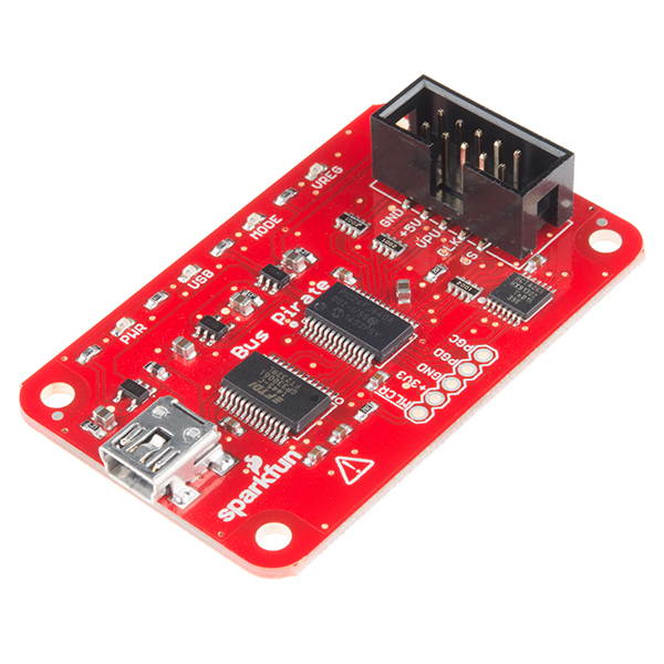
Key Features Macros for common operations Bus traffic sniffers (SPI, I2C) A bootloader for easy firmware updates Transparent USB->serial mode The Bus Pirate v 3.6 a, created by & nbsp; Ian Lesnet, is a troubleshooting tool that communicates between a PC and any embedded device over 1-wire, 2-wire, 3-wire, UART, I2C, SPI, and HD44780 LCD protocols - all at voltages from 0- 5.5VDC. This product eliminates a ton of early prototyping effort when working with new or unknown chips. Working with the Bus Pirate is simple and effective - type commands into a terminal on your computer, those commands are interpreted by the Bus Pirate and sent via the proper protocol. The Pirate will also interpret data sent from your embedded device back to your computer terminal. The main components of the Bus Pirate are the PIC24FJ64 processor and a FT232RL USB-to-Serial chip. A Mini-B USB connector that has also been populated on the board, provides the power to the Bus Pirate and allows you to interact with via your PC. The major difference in this version of the Bus Pirate comes from the shrouded 0.1" pitch 2x5 pin header, which has been flipped around to help standardize this board. Additionally every pin on this header has been labeled, eliminating the need for a separate I/O pin description document like with earlier versions. Item Specific 5.5V tolerant pins 6V measurement probe 1Hz - 40MHz frequency measurement 1kHz - 4MHz pulse-width modulator, frequency generator On-board multi-voltage pull-up resistors On-board 3.3 volt and 5volt power supplies with software reset 10Hz - 1MHz low-speed logic analyzer Scriptable from Perl, Python, etc. Access to PIC24FJ64 ICSP programming port Some programming skills required Bus pirate cable not included
SparkFun ESP8266 Thing Starter Kit for Internet of Things WiFi Development Includes headers jumper wires breadboard Serial breakout Mico-B USB Cable a
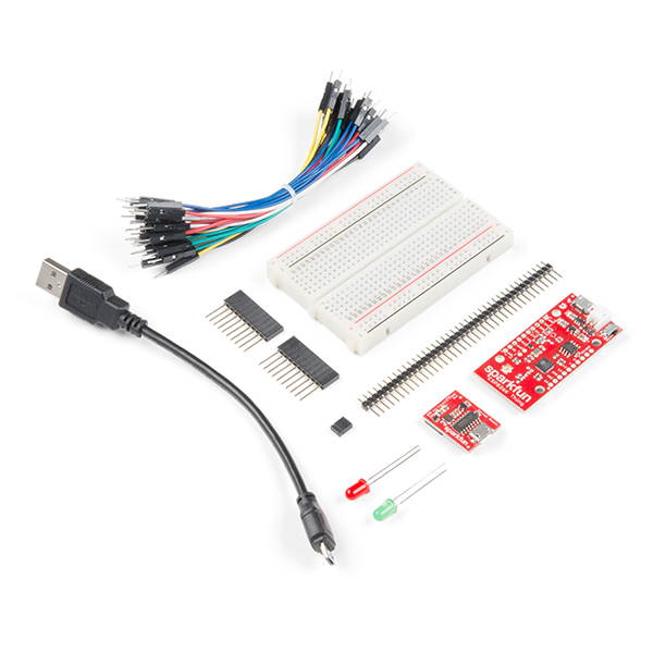
The SparkFun ESP8266 Thing Starter Kit is a great place to start learning about the Internet of Things (IoT)! Inside this kit you will find a ESP8266 Thing, a Serial Basic Breakout to program it (and USB cable), jumper wires, breadboard, LEDs, and plenty of headers. We've also included a pair of stackable 10-pin headers as well as 40 regular headers to connect your Serial Basic Breakout to the Thing or breadboard. If you have ever been interested in learning about IoT, Arduino, and wireless solutions, the SparkFun ESP8266 Thing Starter Kit is a perfect place to start!The SparkFun ESP8266 Thing is a breakout and development board for the ESP8266 WiFi SoC – a leading platform for Internet of Things (IoT) or WiFi-related projects. The Thing is low-cost and easy to use, and Arduino IDE integration can be achieved in just a few steps. We've made the ESP8266 easy to use by breaking out all of the module’s pins, adding a LiPo charger, power supply, and all of the other supporting circuitry it requires.Why the name? We lovingly call it the “Thing” due to it being the perfect foundation for your Internet of Things project. The Thing does everything from turning on an LED to posting data with datastream, and can be programmed just like any microcontroller. You can even program the Thing through the Arduino IDE by installing the ESP8266 Arduino addon.Note: You may want to either use a second USB cable to power the board while programming or connect the solder jumper on the back of the board to provide power over the FTDI port.Includes:SparkFun ESP8266 ThingSparkFun Serial Basic Breakout - CH340GJumper Wires 4in M/M (30 pack)MicroB USB CAble - 6inBreadboardStackable Headers - 10 pin x2LED - Basic Green 5mmLED - Basic Red 5mmJumper 2 pinBreak Away Headers - Straight (40 pins)
SparkFun Motor Driver - Dual TB6612FNG (1A)
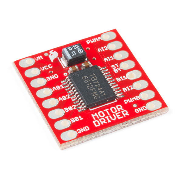
Key Features Built-in thermal shutdown circuit and low-voltage detecting circuit Control up to two DC motors at a constant current of 1.2A Two motor outputs (A and B) can be separately controlled & nbsp; Comes with all components pre-installed The TB6612FNG Motor Driver can control up to two DC motors at a constant current of 1.2A ( 3.2A peak). Two input signals (IN1 and IN2) can be used to control the motor in one of four function modes: CW, CCW, short-brake and stop. The two motor outputs (A and B) can be separately controlled, and the speed of each motor is controlled via a PWM input signal with a frequency up to 100kHz. The STBY pin should be pulled high to take the motor out of standby mode. Logic supply voltage (VCC) can be in the range of 2.7 -- 5.5VDC, while the motor supply (VM) is limited to a maximum voltage of 15VDC. The output current is rated up to 1.2A per channel (or up to 3.2A for a short, single pulse). This little board comes with all components installed as shown. Decoupling capacitors are included on both supply lines. All pins of the TB6612FNG are broken out to two 0.1" pitch headers; the pins are arranged such that input pins are on one side and output pins are on the other. Item Specifics Power supply voltage: VM = 15V max, VCC = 2.7 -- 5.5V Output current: Iout = 1.2A (average) / 3.2A (peak) Standby control to save power CW/CCW/short-brake/stop motor control modes All pins of the TB6612FNG broken out to 0.1" spaced pins Filtering capacitors on both supply lines
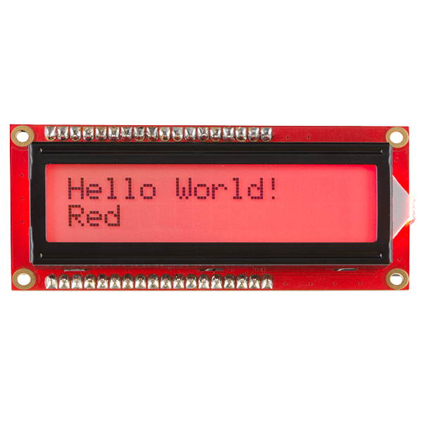
SparkFun Basic 16x2 Character LCD - RGB Backlight 5V
Key Features 16x2 character LCDs & nbsp; Change the backlight of this display to any color you want by controlling the three backlight levels Uses an extremely common parallel interface This is similar to other 16x2 character LCDs that you & #39; ve seen before but with one vibrant difference: The backlight is actually an RGB LED. This means that you can change the backlight of this display to any color you want by controlling the three backlight levels. It also utilizes an extremely common parallel interface so code is freely available. You will need ~11 general I/O pins to interface to this LCD screen, plus an extra 3 pins for the RGB backlight. Note: It is recommended to use a current limiting resistor with the backlight colors. You can burn out your LEDs if you do not use a current limiting resistor. Try using a 1k Ohm resistor. The backlight is controlled by pins 18, 17, and 16. Item Specifics 16x2 LCD Some soldering skills required Basic programming skills required Competent electrical prototyping skills required
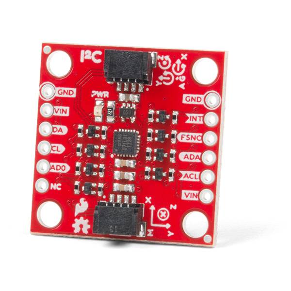
SparkFun 9DoF IMU Breakout-ICM-20948 Low power I2C & SPI enabled 9 axis motion tracking Includes Logic shifter Qwiic connection GPIO pins Digital Moti
The SparkFun 9DoF IMU Breakout incorporates all the amazing features of Invensense's ICM-20948 into a Qwiic-enabled breakout board complete with a logic shifter and broken out GPIO pins for all your motion sensing needs. The ICM-20948 itself is an extremely low powered, I2C and SPI enabled 9-axis motion tracking device that is ideally suited for smartphones, tablets, wearable sensors, and IoT applications. Utilizing our handy Qwiic system, no soldering is required to connect it to the rest of your system. However, we still have broken out 0.1"-spaced pins in case you prefer to use a breadboard.In addition to the 3-Axis Gyroscope with four selectable ranges, 3-Axis Accelerometer, again with four selectable ranges, and 3-axis magnetometer with an FSR to ±4900µT, the ICM-20948 also includes a Digital Motion Processor that offloads the computation of motion sensing algorithms from the detectors, allowing optimal performance of the sensors. We've also broken out all the ICM-20948 pin functionality to GPIO and labeled them I2C on the front, SPI on the back for ease of identification.The SparkFun Qwiic Connect System is an ecosystem of I2C sensors, actuators, shields and cables that make prototyping faster and less prone to error. All Qwiic-enabled boards use a common 1mm pitch, 4-pin JST connector. This reduces the amount of required PCB space, and polarized connections mean you can’t hook it up wrong.I2C at up to 100 kHz (standard-mode) or up to 400 kHz (fast-mode) or SPI at up to 7 MHz for communication with registersI2C Address: 0x69 (0x68 with
Jumper)
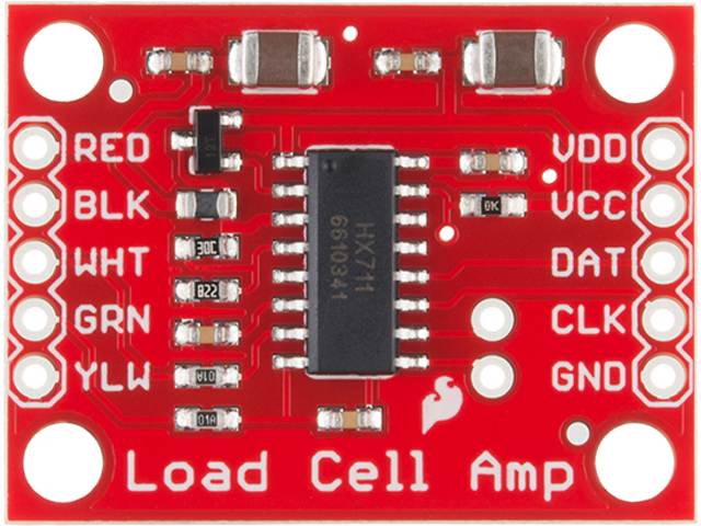
SparkFun Load Cell Amplifier - HX711 Small Breakout Board Read Load Cells to Measure Weight Four-wire Wheatstone Bridge Configuration Connect to Senso
The SparkFun Load Cell Amplifier is a small breakout board for the HX711 IC that allows you to easily read load cells to measure weight. By connecting the amplifier to your microcontroller you will be able to read the changes in the resistance of the load cell, and with some calibration you’ll be able to get very accurate weight measurements. This can be handy for creating your own industrial scale, process control or simple presence detection.This version of the SparkFun Load Cell Amplifier features a few changes that you specifically asked for! We have separated the analog and digital supply, as well as added a 3.3uH inductor and a 0.1uF filter capacitor for digital supply.The HX711 uses a two-wire interface (Clock and Data) for communication. Any microcontroller’s GPIO pins should work, and numerous libraries have been written, making it easy to read data from the HX711. Check the hookup guide below for more information.Load cells use a four-wire Wheatstone bridge configuration to connect to the HX711. These are commonly colored RED, BLK, WHT, GRN and YLW. Each color corresponds to the conventional color coding of load cells:Red (Excitation+ or VCC)Black (Excitation- or GND)White (Amplifier+, Signal+ or Output+)Green (A-, S- or O-)Yellow (Shield)The YLW pin acts as an optional input that is not hooked up to the strain gauge but is utilized to ground and shield against outside EMI (electromagnetic interference). Please keep in mind that some load cells might have slight variations in color coding.
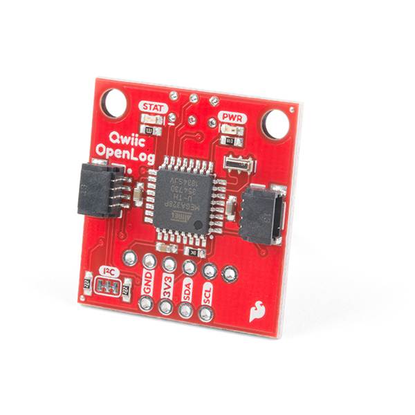
SparkFun Qwiic OpenLog Open-source datalogging Board Works over I2C Supports microSD FAT16/32 cards up to 32GB Configurable baud rates up to 115200bps
The SparkFun Qwiic OpenLog is the smarter and better looking cousin to the extremely popular OpenLog but now we've ported the original serial based interface to I2C! Thanks to the added Qwiic connectors, you can daisy chain multiple I2C devices and log them all without taking up your serial port. The Qwiic OpenLog can store, or "log", huge amounts of serial data and act as a black box of sorts to store all the data that your project generates, for scientific or debugging purposes. Utilizing our handy Qwiic system, no soldering is required to connect it to the rest of your system. However, we still have broken out 0.1"-spaced pins in case you prefer to use a breadboard.Like its predecessor, the SparkFun Qwiic OpenLog runs off of an onboard ATmega328, running at 16MHz thanks to the onboard resonator. The ATmega328 has been sure to feature the Optiboot bootloader loaded, which allows the OpenLog to be compatible with the “Arduino Uno” board setting in the Arduino IDE. It is important to be aware that the Qwiic OpenLog draws approximately 2mA-6mA in idle (nothing to record) mode, however, during a full record the OpenLog can draw 20mA to 23mA depending on the microSD card being used.The Qwiic OpenLog also supports clock stretching, which means it performs even better than the original and will record data up to 20,000 bytes per second at 400kHz. As the receive buffer fills up this OpenLog will hold the clock line, letting the master know that it is busy. Once the Qwiic OpenLog is finished with a task, it releases the clock thus allowing the data to continue flowing without corruption.Note: The SparkFun Qwiic OpenLog supports 64MB to 32GB microSD cards in both FAT16 and FAT32 formats.The SparkFun Qwiic Connect System is an ecosystem of I2C sensors, actuators, shields and cables. All Qwiic-enabled boards use a common 1mm pitch, 4-pin JST connector. Polarized connections mean you can’t hook it up wrong.
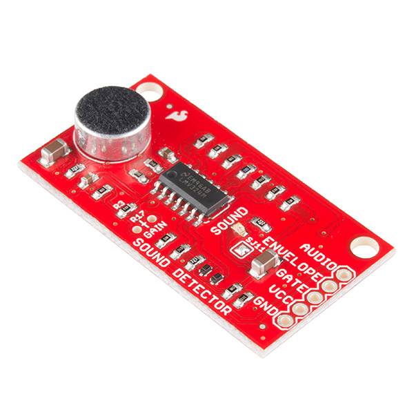
SparkFun Sound Detector Audio sensing breakout Three different outputs Audio Presence of sound Binary indication Amplitude Analog representation VCC:
The SparkFun Sound Detector is a small and very easy to use audio sensing board with three different outputs. The Sound Detector not only provides an audio output, but also a binary indication of the presence of sound, and an analog representation of its amplitude. The 3 outputs are simultaneous and independent, so you can use as many or as few as you want at once.The envelope output allows you to easily read amplitude of sound by simply measuring the analog voltage. Gain can be adjusted with a through-hole resistor, to change the threshold of the binary (gate) output pin as well. Check the hookup guide below for more information about setting gain.Each of the three output signals is present on the .1" header at the edge of the board. They are active simultaneously. If you aren’t using one in your particular application, simply leave that pin disconnected.VCC: 3.5V to 5.5V. Ideal voltage is 5V.
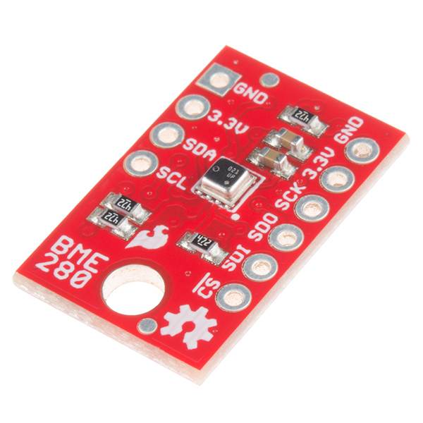
SparkFun Atmospheric Sensor Breakout - BME280 Measure Weather with Barometric pressure Relative Humidity Temperature Small Footprint I2C & SPI Communi
The SparkFun BME280 Atmospheric Sensor Breakout is the easy way to measure barometric pressure, humidity, and temperature readings all without taking up too much space. Basically, anything you need to know about atmospheric conditions you can find out from this tiny breakout. The BME280 Breakout has been design to be used in indoor/outdoor navigation, weather forecasting, home automation, and even personal health and wellness monitoring.The on-board BME280 sensor measures atmospheric pressure from 30kPa to 110kPa as well as relative humidity and temperature. The breakout provides a 3.3V SPI interface, a 5V tolerant I2C interface (with pull-up resistors to 3.3V), takes measurements at less than 1mA and idles less than 5µA. The BME280 Breakout board has 10 pins, but no more than six are used at a single time. The left side of the board provide power, ground, and I2C pins. The remaining pins which provide SPI functionality and have another power and ground, are broken out on the other side.Note: The breakout does NOT have headers installed and will need to purchased and soldered on yourself.Operation Voltage: 3.3VI2C & SPI Communications InterfaceTemp Range: -40C to 85CHumidity Range: 0 - 100% RH, =-3% from 20-80%Pressure Range: 30,000Pa to 110,000Pa, relative accuracy of 12Pa, absolute accuracy of 100PaAltitude Range: 0 to 30,000 ft (9.2 km), relative accuracy of 3.3 ft (1 m) at sea level, 6.6 (2 m) at 30,000 ft.Incredibly Small
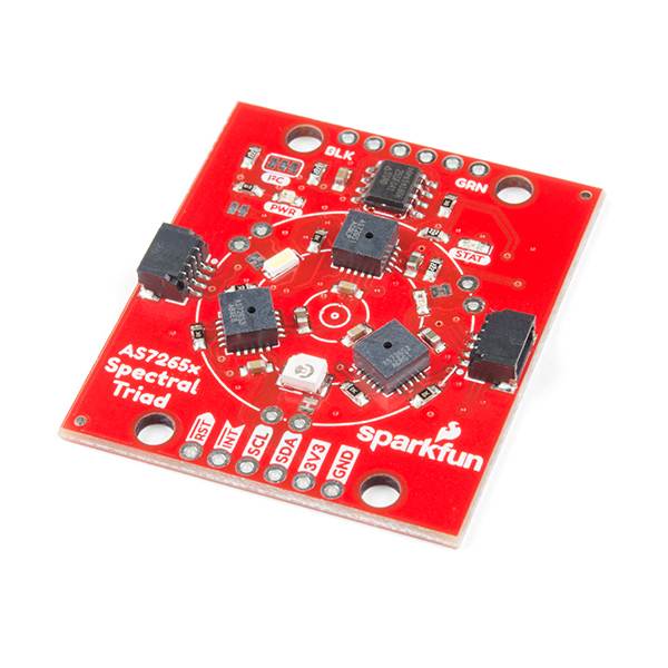
SparkFun Triad Spectroscopy Sensor - AS7265x Optical inspection breakout Combines visible UV IR LEDs with three spectral sensors Vcc 3.3V Qwiic I2C Se
The SparkFun Triad Spectroscopy Sensor is a powerful optical inspection sensor. Three AS7265x spectral sensors are combined alongside a visible, UV, and IR LEDs to illuminate and test various surfaces for light spectroscopy. The Triad is made up of three sensors; the AS72651, the AS72652, and the AS72653 and can detect the light from 410nm (UV) to 940nm (IR). In addition, 18 individual light frequencies can be measured with precision down to 28.6 nW/cm2 and accuracy of +/-12%. Utilizing our handy Qwiic system, no soldering is required to connect it to the rest of your system. However, we still have broken out 0.1"-spaced pins in case you prefer to use a breadboard.The SparkFun Triad Spectroscopy Sensor communicates over I2C by default or over 115200bps serial. We’ve written a fully formed Arduino library to access all the various features include taking readings and illuminating LEDs all over the Qwiic I2C interface. In addition, the Triad can be setup to communicate over serial. The serial interface uses an AT command set.What can you do with light spectroscopy? It’s an amazing field of study, and the SparkFun Triad brings what used to be prohibitively expensive equipment to the desktop. The AS7265x should not be confused with highly complex photon spectrometers, but the sensor array does give the user the ability to measure and characterize how different materials absorb and reflect 18 different frequencies of light. We’ve also written a full Arduino library that makes reading and interacting with the Triad simple and easy!The SparkFun Qwiic Connect System is an ecosystem of I2C sensors, actuators, shields and cables that make prototyping faster and less prone to error. All Qwiic-enabled boards use a common 1mm pitch, 4-pin JST connector. This reduces the amount of required PCB space, and polarized connections mean you can’t hook it up wrong.
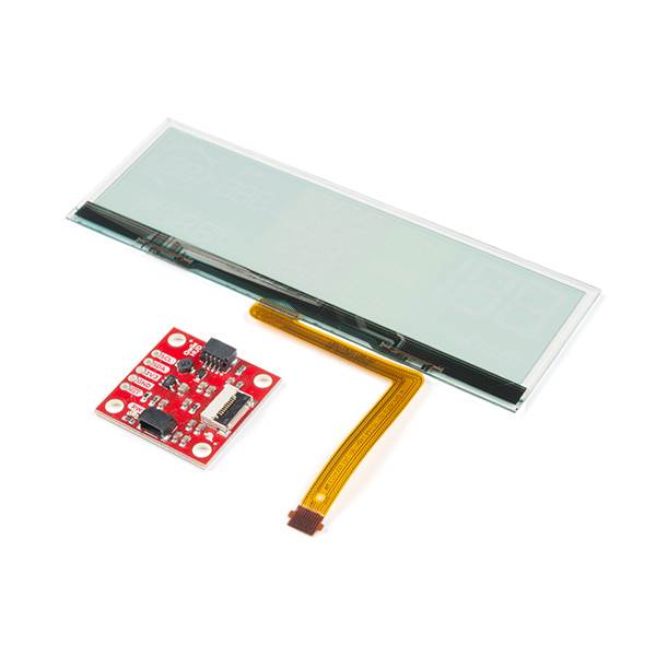
SparkFun Transparent OLED HUD Breakout Brilliant LCD Visible in Daylight Qwiic I2C protocol No Soldering Required or Breadboard-able Area-colored segm
Clear screens are no longer a thing of the Sci-Fi world! The Qwiic Transparent OLED HUD is SparkFun's answer to all of your futuristic transparent HUD needs. Designed for use in vehicle heads-up displays, this OLED panel is brilliant in the dark but easily visible in daylight. The display is "area colored" meaning that while no one segment can change colors, there are different colored segments on the display.The SparkFun Transparent OLED Breakout allows you to easily control the display using the I2C protocol and includes a voltage step-up to generate the panel's 12V driving voltage from Qwiic's 3.3V bus. To make things even easier, we've thrown together an Arduino library so that doing things like changing the speedometer read out is as easy as calling setSpeedometer() in your sketch. Utilizing our handy Qwiic system, no soldering is required to connect it to the rest of your system. However, we still have broken out 0.1"-spaced pins in case you prefer to use a breadboard.The Arduino sketch required to drive this display requires quite a bit of dynamic memory, meaning that it is not going to fit on a smaller controller like an ATmega328. Any controller with larger RAM should have no problem. It has been tested to run very well on an Arduino Mega 2560. In addition, your 3.3v source should be robust enough to supply around 400mA to the display.The SparkFun Qwiic Connect System is an ecosystem of I2C sensors, actuators, shields and cables that make prototyping faster and less prone to error. All Qwiic-enabled boards use a common 1mm pitch, 4-pin JST connector. This reduces the amount of required PCB space, and polarized connections mean you can’t hook it up wrong.Includes:1 x Transparent OLED Display1 x Qwiic HUD Breakout BoardI2C Addresses: 0x30, 0x312x Qwiic Connectors
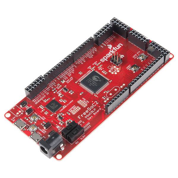
SparkFun FreeSoC2 Development Board - PSoC5LP ARM Cortex-M3
Key Features Features of programmable devices and microcontroller-type systems-on-chips in one package Two onboard processors: a CY8C5868LTI-LP039 and a CY8C5888AXI-LP096 Write code for the board in the standard Arduino IDE Both processors contain a Cortex-M3 core, 256kB of flash memory, 64kB of SRAM and 2kB of EEPROM This is the FreeSoC2 Development Board, SparkFun & rsquo; s take on the PSoC5LP ARM Cortex. The PSoC (Programmable System-on-Chip) allows any function to be routed to any pin and includes a number of programmable blocks, which allow the user to define arbitrary digital and analog circuits for their specific application. SparkFun & rsquo; s FreeSoC2 board has two processors onboard: a CY8C5868LTI-LP039 and a CY8C5888AXI-LP096. The former serves as a debugger/programmer for the latter, which is the target upon which your application code will be installed. The only significant differences between the two are package size and clock speed. The target is in a TQFP-100 package, which provides 72 I/O pins versus the debugger & rsquo; s QFN-68 package and 48 I/O pins, and the target can operate at 80MHz versus the debugger & rsquo; s 67MHz limit. Additionally, the FreeSoC2 can support 5V and 3.3V I/O voltages. With a simple upload of new firmware, the Arduino core has been ported to the PSoC5LP, so you can write code for the board in the standard Arduino IDE. The board duplicates the functionality of an Arduino Uno R3 & rsquo; s various hardware peripherals on the pins, so many examples, libraries and shields will work on this board. However, to get the most out of the device, you will need to use the PSoC Creator IDE. Item Specific 256kB of Flash Memory (each core) 64kB of SRAM (each core) 2kB of EEPROM (each core) Arduino Uno R3-type headers Some basic soldering skills required Experienced programming skills required PSoC Creator software is Windows-only
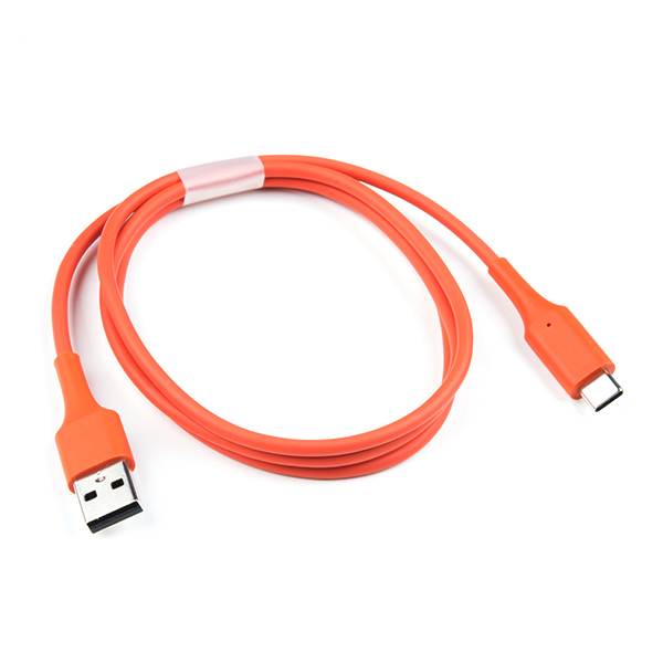
SparkFun SuzyQable - ChromeOS Debug Cable
Key Features: 2-port USB hub, and a Rp1A5+RpUSB on the CC pins to activate debug mode Quickly access debugging, recovery, and developer features exposed through some of the USB-C ports on ChromeOS Recommended for advanced users and professionals The SuzyQable allows developers, hobbyists, and others to quickly access debugging, recovery, and developer features exposed through some of the USB-C ports on ChromeOS and other Google devices. To be honest with everyone interested in picking up this cable: is not for the average developer and is recommended for advanced users and professionals. Internally, the SuzyQable has a 2-port USB hub, and a Rp1A5+RpUSB on the CC pins to activate debug mode. One USB port goes to D+/D-, the other USB port goes to SBU1+SBU2. When you attach it to a supporting port, Google devices enable a USB port on SBU which exposes a bunch of endpoints, including UART (accessible with standard serial drivers) for both the embedded controller and Linux consoles, and, depending on the state of your system, a way to flash firmware using the open-source servod software and flashrom. Basically, the SuzyQable is designed to replace ServoV2 for the most common use-cases, and uses the same software (unless you just want terminal access, in which case you don & #39; t need any software). The USB device the cable talks to gets updates with ChromeOS, so features will be added or changed as development continues. All ChromeOS devices moving forwards will support this cable, starting with the Acer C101 and Pixelbook. Item Specifics Experienced programming skills required
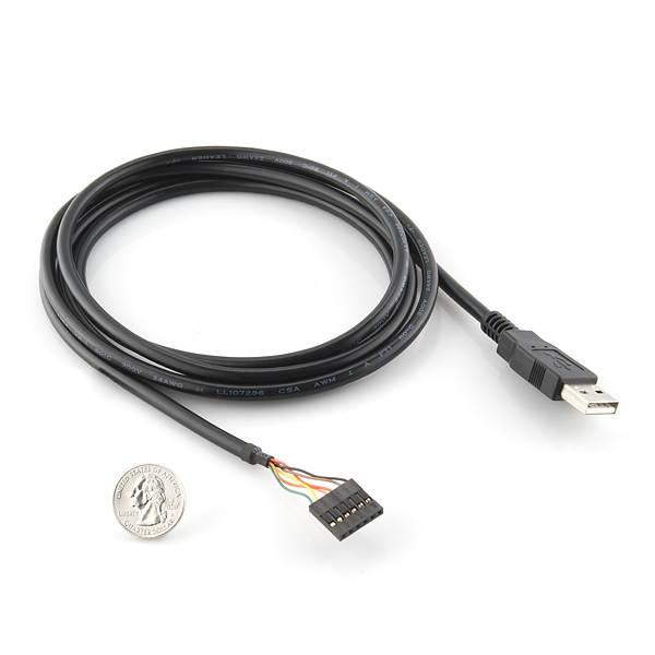
SparkFun FTDI Cable 5V
Key Features Program your Arduino Pro, Pro Mini and Lilypad Designed around an FT232RQ USB to Serial (TTL level) converter allows for a simple way to connect TTL interface devices to USB 5V I/O The FTDI cable is a USB to Serial (TTL level) converter which allows for a simple way to connect TTL interface devices to USB. The I/O pins of this FTDI cable are configured to operate at 5V. The FTDI cable is designed around an FT232RQ, which is housed in a USB A connector. The other side of the cable is terminated with a 0.1" pitch, 6-pin connector with the following pinout: RTS, RX, TX, 5V, CTS, GND (RTS is the green cable and GND is black). This cable has the same pinout and functionality as our & nbsp; FTDI Basic Breakout & nbsp; board; you can use it to program your & nbsp; Arduino Pro, & nbsp; Pro Mini & nbsp; and & nbsp; Lilypad. For use with those boards, align the black and green wires of the FTDI cable with the & #39; BLK & #39; and & #39; GRN & #39; labels on the PCB. There are pros and cons to the FTDI Cable vs the FTDI Basic. The FTDI Basic has great LED indicators, but requires a Mini-B cable. The FTDI Cable is well protected against the elements, but is large and cannot be embedded into a project as easily. The FTDI Basic uses DTR to cause a hardware reset where the FTDI cable uses the RTS signal. Item Specifics 0.1" pitch 6-pin connector Pinout: RTS, RX, TX, 5V, CTS, GND (RTS is the green cable and GND is black)
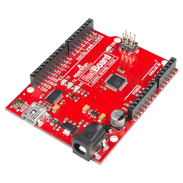
SparkFun RedBoard - Programmed Breadboard-able Development board (Arduino-Compatible)
Key Features ATmega328 microcontroller with Optiboot (UNO) Bootloader Programmable over a USB Mini-B cable using the Arduino IDE On-board power regulator handles 7 to 15VDC Power the RedBoard over USB or through the barrel jack The SparkFun RedBoard combines the simplicity of the UNO & #39; s Optiboot bootloader (which is used in the Pro series), the stability of the FTDI and the R3 shield compatibility of the latest Arduino UNO R3. The RedBoard can be programmed over a USB Mini-B cable using the Arduino IDE: Just plug in the board, select "Arduino UNO" from the board menu and you & #39; re ready to upload code. RedBoard has all of the hardware peripherals you know and love: 14 Digital I/O pins with 6 PWM pins, 6 Analog Inputs, UART, SPI and external interrupts. The SDA, SCL and IOREF pins are broken out so the RedBoard will be compatible with future shields. This version adds an SMD ISP header for use with shields. You can power the RedBoard over USB or through the barrel jack. The on-board power regulator can handle anything from 7 to 15VDC. Check out the related items below for a compatible wall-wart power supply. Item Specifics USB Programming Facilitated by the Ubiquitous FTDI FT231X Input voltage - 7-15V 0-5V outputs with 3.3V compatible inputs 14 Digital I/O Pins (6 PWM outputs) 6 Analog Inputs ISP Header 32k Flash Memory 16MHz Clock Speed All SMD Construction R3 Shield Compatible Red PCB
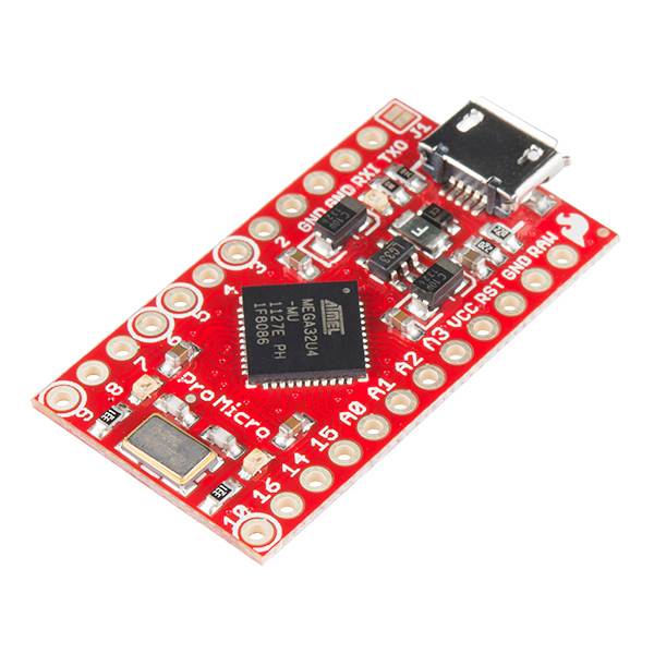
SparkFun Pro Micro - 3.3V/8MHz
Key Features ATMega 32U4 running at 3.3V /8MHz Supported under Arduino IDE v 1.0. 1 On-Board micro-USB connector for programming SparkFun & #39; s Smallest Arduino-Compatible Board Yet The Pro Micro is similar to the Pro Mini except with an ATmega32U4 on board. The USB transceiver inside the 32U4 allows us to add USB connectivity on-board and do away with bulky external USB interface. This tiny little board does all of the neat-o Arduino tricks that you & #39; re familiar with: 9 channels of 10-bit ADC, 5 PWM pins, 12 DIOs as well as hardware serial connections Rx and Tx. Running at 8MHz and 3.3V, this board will remind you a lot of your other favorite Arduino-compatible boards but this little guy can go just about anywhere. This is the 3.3V version so, as always, keep in mind the limits of system voltage and so forth. The lower system voltage also has its advantages, though, like ease of use with many common 3.3V sensors. There is a voltage regulator on board so it can accept voltage up to 12VDC. If you & #39; re supplying unregulated power to the board, be sure to connect to the "RAW" pin on not VCC. Item Specifics 9 - 10-bit ADC pins 12 - Digital I/Os (5 are PWM capable) Rx and Tx Hardware Serial Connections Size: 1.3 x 0.7" Some soldering skills required Fundamental programming skills required Competent electrical prototyping skills required
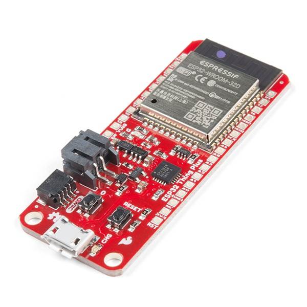
SparkFun Thing Plus - ESP32 WROOM
Key Features: ESP32 WROOM: Powerful WiFi and Bluetooth MCU module that targets a wide variety of applications 16MB of flash memory, 520kB of internal SRAM, an integrated 802.11 BGN WiFi transceiver and dual-mode Bluetooth capabilities Feather compatible Handy Qwiic Connect System which means no soldering or shields are required to connect it to the rest of your system The SparkFun ESP32 Thing Plus is the next step to get started with Espressif IoT ideations while still enjoying all the amenities of the original ESP32 Thing. Espressif's ESP32 WROOM is a powerful WiFi and Bluetooth MCU module that targets a wide variety of applications. At the core of this module is the ESP32-D0WDQ6 chip which is designed to be both scalable and adaptive. To make the Thing Plus even easier to use, a few pins were moved around to make the board Feather compatible and it utilizes our handy Qwiic Connect System which means no soldering or shields are required to connect it to the rest of your system! The ESP32 Thing plus integrates a rich set of peripherals, ranging from capacitive touch sensors, Hall sensors, SD card interface, Ethernet, high-speed SPI, UART, I2S and I2C. Thanks to the onboard ESP32 WROOM module, the SparkFun Thing Plus features 16MB of flash memory, 520kB of internal SRAM, an integrated 802.11 BGN WiFi transceiver and dual-mode Bluetooth capabilities, and a JST connector to plug in a LiPo battery. Item Specifics Size: 2.30 x 0.90 Inches Xtensa® dual-core 32-bit LX6 microprocessor Up to 240MHz clock frequency 16MB of flash storage 520kB internal SRAM Integrated 802.11 BGN WiFi transceiver Integrated dual-mode Bluetooth (classic and BLE) 2.3 to 3.6V operating range 21 GPIO 8-electrode capacitive touch support Hardware accelerated encryption (AES, SHA2, ECC, RSA-4096) 2.5 µA deep sleep current
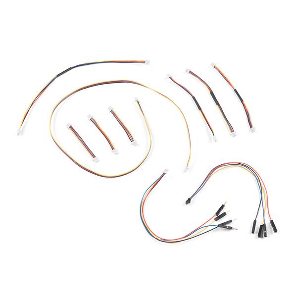
SparkFun Qwiic Cable Kit Hook Up I2C Qwiic Development Boards in No Time No Soldering Required Includes 10 Cables Different Lengths & Styles Breadboar
The Spark Fun Qwiic Connect System is constantly growing in popularity with makers. So to make it even easier to get started, we've assembled this Qwiic Cable Kit for everyone. If you aren't sure which Qwiic cable to use, this handy box includes all of them allowing you to save a little money and time! It has a little something for everyone. The Spark Fun Qwiic Cable Kit includes 10 cables of various lengths and styles that will get your Qwiic boards connected together, to a development platform, or to a breadboard. Each Qwiic Cable's wires have been color coded to red, black, blue and yellow with 1mm JST termination. The Spark Fun Qwiic connect system is an ecosystem of I2C sensors, actuators, shields and cables that make prototyping faster and less prone to error. All Qwiic-enabled boards use a common 1mm pitch, 4-pin JST connector. This reduces the amount of required PCB space, and polarized connections mean you can’t hook it up wrong. Includes: 3x Qwiic Cable - 50mm 3x Qwiic Cable - 100mm 1x Qwiic Cable - 200mm 1x Qwiic Cable - 500mm 1x Qwiic Cable - Breadboard Jumper (4-pin) 1x Qwiic Cable - Female Jumper (4-pin) All Qwiic cables have the following color scheme and arrangement: Black = GND Red = 3.3V Blue = SDA Yellow = SCL
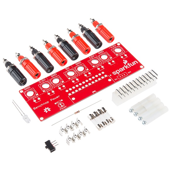
SparkFun Benchtop Power Board Kit
Key Features Take advantage of your power supply to create a benchtop power supply Run almost any of your embedded electronics projects Created to provide quick access to the typical voltages needed when developing physical computing projects Access to four different voltages ( 3.3V, 5V, 12V and -12V) each with their own replaceable 5A fuse This board will let you take advantage of your power supply to create a benchtop power supply with enough juice to run almost any of your embedded electronics projects. The benchtop power board kit was created to provide quick access to the typical voltages needed when developing physical computing projects (embedded systems). After assembling the kit you & #39; ll have access to four different voltages ( 3.3V, 5V, 12V and -12V) each with their own replaceable 5A fuse. Each power rail has a corresponding ground connection; all of the power rails are brought out to a binding post. The benchtop power board should be powered by a standard computer power supply with an ATX connector. With this rev we have finally added a power switch and made each standoff to a more appropriate height to fit the mounting posts. This kit is simple to put together and shouldn & #39; t take more than 30-45 minutes for a beginner. Item Specific Basic soldering skills required Some electrical prototyping skills required
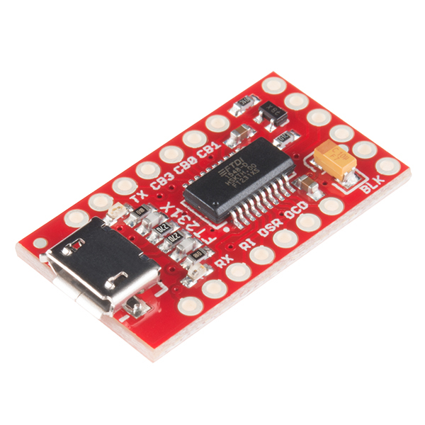
SparkFun FT231X Breakout
Key Features Pin-out matches the FTDI cable to work with official Arduino and cloned Arduino boards Auto-reset any Arduino board that has the reset pin brought out to a 6-pin connector Uses a common microUSB jack Jumper allows the VCC output to be configured to either 3.3V or 5V Introducing the SparkFun FT231X Breakout board, complete with the full UART hardware handshake feature! The pin-out of this board matches the FTDI cable to work with official Arduino and cloned Arduino boards. It can also be used for general serial applications. This board still brings out the DTR pin as opposed to the RTS pin of the FTDI cable. The DTR pin allows an Arduino target to auto-reset when a new Sketch is downloaded. This is a really nice feature to have and allows a sketch to be downloaded without having to hit the reset button. This board will auto-reset any Arduino board that has the reset pin brought out to a 6-pin connector. One of the features of this board is a jumper on the back, which allows the VCC output to be configured to either 3.3V or 5V. This board ships default to 5V, but you can cut the default trace and add a solder jumper if you need to switch to 3.3V. It should be noted that the max input of the FT231X is only 3.3V, but it can operate down to 1.8V with external pull-ups and is also 5V tolerant. Item Specific Basic soldering skills required Fundamental programming skills needed
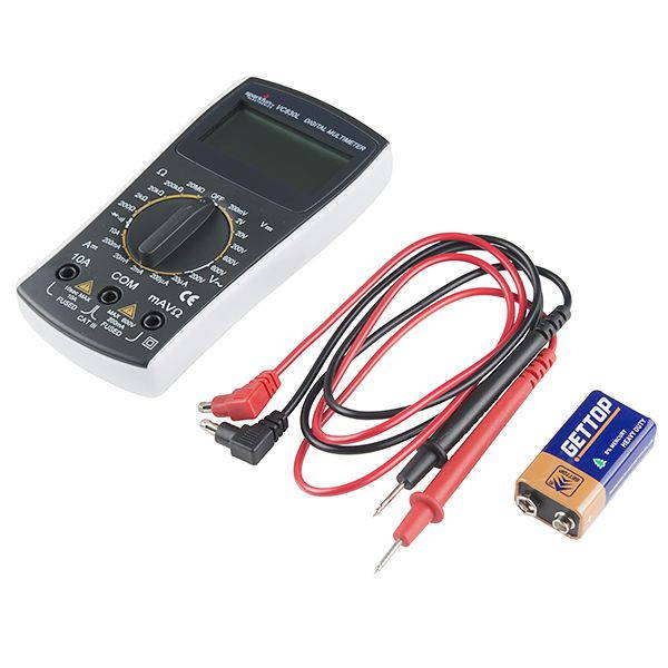
SparkFun Digital Multimeter - Basic
Key Features An essential tool in every electronic enthusiasts arsenal Loud continuity sound, current/voltage sense, and quality probes Measure DC and AC voltage, DC current, resistance, continuity, and test diodes 9V battery included The digital multimeter (DMM) is an essential tool in every electronic enthusiasts arsenal. The SparkFun Digital Multimeter, however, is not your average multimeter, it features a loud continuity sound, current/voltage sense, and quality probes. You can use the multimeter to measure DC and AC voltage, DC current, resistance, continuity, and test diodes. With this version we & #39; ve done away with the bright flashy colors that can get us into trouble and gone with a nice, neutral gray. This multimeter should provoke no strong feelings one way or the other, we know this because our guts say "maybe. " This isn & #39; t your expensive, flashy type of multimeter, this is for all those starving students that need to buy their first good, low-cost digital multimeter. This meter doesn & #39; t have the ability to auto-power off, it isn & #39; t capable of auto-ranging, and it won & #39; t be able to measure frequency. However, with this multimeter you WILL be able to measure DC Voltage from 200mV to 600V, AC Voltage from 200V and 600v, DC Current between 200uA to 10A, and Resistance from 0 to 20M Ohm. Battery life lasted more than 170 hours (7 days) before the included 9V gave out! Item Specific 1 - Digital Multimeter 1 - 9V Battery 2 - Testing Probes DC Voltage - 200mV/2V/20V/200V/600V AC Voltage - 200V/600V DC Current - 200uA/20mA/200mA/10A Resistance - 0 to 20M Ohm Continuity Buzzer Diode Test Max Display: 1999
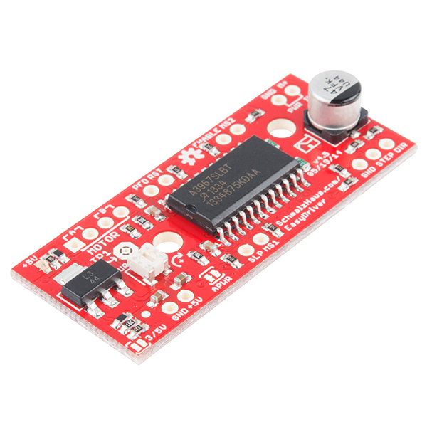
SparkFun EasyDriver Stepper Motor Driver
Key Features A3967 Microstepping Driver Change microstepping resolution to full, half, quarter and eighth steps (defaults to eighth) Compatible with 4, 6, and 8 wire stepper motors of any voltage Adjustable current control from 150mA/phase to 700mA/phase Power supply range from 6V to 30V. The higher the voltage, the higher the torque at high speeds The EasyDriver is a simple to use stepper motor driver, compatible with anything that can output a digital 0 to 5V pulse (or 0 to 3.3V pulse if you solder SJ2 closed on the EasyDriver). The EasyDriver requires a 6V to 30V supply to power the motor and can power any voltage of stepper motor. The EasyDriver has an on board voltage regulator for the digital interface that can be set to 5V or 3.3V. Connect a 4-wire stepper motor and a microcontroller and you & #39; ve got precision motor control! EasyDriver drives bi-polar motors, and motors wired as bi-polar. I. e. 4, 6, or 8 wire stepper motors. This EasyDriver V 4.5 has been co-designed with Brian Schmalz. It provides much more flexibility and control over your stepper motor, when compared to older versions. The microstep select (MS1 and MS2) pins of the A3967 are broken out allowing adjustments to the microstepping resolution. The sleep and enable pins are also broken out for further control. Item Specifics MS1 and MS2 pins broken out Basic soldering skills required Competent programming skills required Competent robotics skills required Some electrical prototyping skills required Note: Do not connect or disconnect a motor while the driver is energized. This will cause permanent damage to the A3967 IC.
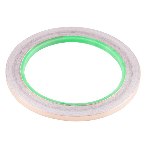
SparkFun Conductive Adhesive Copper Tape - 5mm x 50ft
Key Features: Backed by a conductive adhesive 5mm wide and comes in rolls of 50 feet Perfect for more precise projects Copper tape has countless applications in electronics from creating low-profile traces for electrical components to RF-shielding and antenna-making. Copper tape is even used to join things together using solder, like the stained glass on Tiffany lamps. The 5mm copper tape is a great option for making paper circuit traces. It & apos; s a better option compared to using the 2" copper tape. Item Specifics Length: 50 & apos; Width: 5mm Thickness: about 3 mil Adhesive backing: Conductive
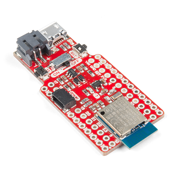
SparkFun Pro nRF52840 Mini - Bluetooth Development Board
Key Features: Breakout and development board for Nordic Semiconductor & rsquo; s nRF52840 Peripheral-multiplexing Every I/O peripheral you could need Integrated 2.4GH z radio with support for Bluetooth Low Energy (BLE), Bluetooth 5, ANT, Nordic & #39; s proprietary RF protocol The SparkFun Pro nRF52840 Mini is a breakout and development board for Nordic Semiconductor & rsquo; s nRF52840 & ndash; a powerful combination of ARM Cortex-M4 CPU and 2.4GH z Bluetooth radio. This mini development board for the nRF52840 breaks out most of the critical I/O pins including GPIO and those needed for power while maintaining a small footprint that nearly matches that of the Arduino Pro Mini (except those covered by the Qwiic Connector). It features a USB interface (using the nRF52840 & rsquo; s native USB support), which can be used to program, power, and communicate with the chip making it able to be used for any purpose (UART, I2C, SPI) that those of the Arduino Pro Mini could. The Pro nRF52840 Mini features a Raytac MDBT50Q-P1M module. This module connects the nRF52840 to a trace antenna, fits the IC into an FCC-approved footprint, and also includes a lot of the decoupling and timing mechanisms that would otherwise be required for a bare nRF52840 design. Also included onboard is a LiPo battery charger, a Qwiic connector, an on/off switch, a reset switch, and a user LED/button. Item Specifics ARM Cortex-M4 CPU with floating point unit (FPU) 1MB internal Flash 256kB internal RAM USB peripherals UART -- Serial interfaces with support for hardware flow-control if desired. I2C interface SPI -- If you prefer the 3+-wire serial interface Analog-to-digital converters (ADC) -- Eight pins on the nRF52840 Mini Breakout support analog inputs PWM -- Timer support on any pin means PWM support for driving LEDs or servo motors. Real-time clock (RTC)
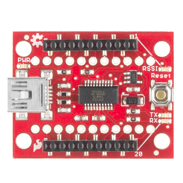
SparkFun XBee Explorer USB
Key Features Simple to use, USB to serial base unit for the Digi XBee line Works with all XBee modules including the Series 1 and Series 2.5, standard and Pro version Direct access to the serial and programming pins on the XBee unit FT231X USB-to-Serial converter This is a simple to use, USB to serial base unit for the Digi XBee line. This unit works with all XBee modules including the Series 1 and Series 2.5, standard and Pro version. Plug the unit into the XBee Explorer, attach a mini USB cable, and you will have direct access to the serial and programming pins on the XBee unit. The highlight of this board is an FT231X USB-to-Serial converter. That & rsquo; s what translates data between your computer and the XBee. There & rsquo; s also a reset button, and a voltage regulator to supply the XBee with plenty of power. In addition, there are four LEDs that & rsquo; ll help if you ever need to debug your XBee: RX, TX, RSSI (signal-strength indicator), and power indicator. This board also breaks out each of the XBee & rsquo; s I/O pins to a pair of breadboard-compatible headers. So if you want to make use of the XBee & rsquo; s extended functionality, you can solder some header pins into those, or even just solder some wire. Item Specifics XBee not included Note: This board cannot source the power required for the Cellular XBee line. It will only work with the 802.15. 4 variants.
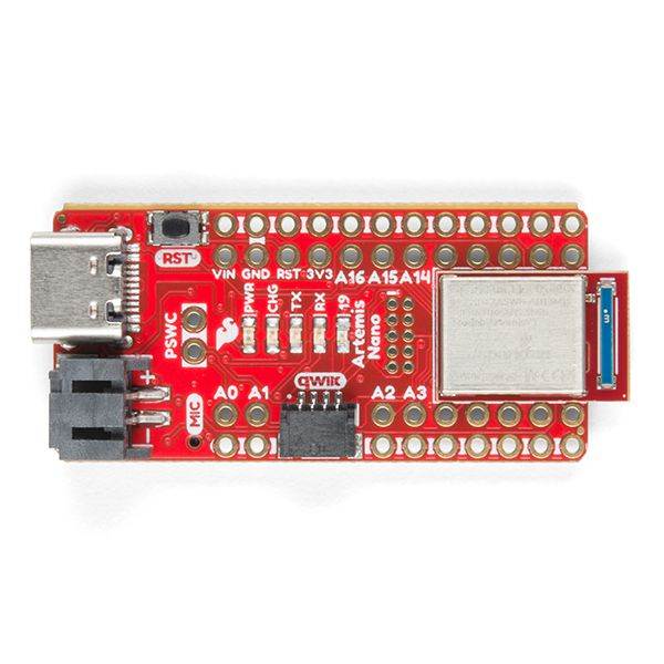
SparkFun RedBoard Artemis Nano Machine Learning Development Board
Key Features: This board is easy to implement into very small projects With 1MB flash and 384k RAM you & #39; ll have plenty of room for your sketches Runs at 48MHz with a 96MHz turbo mode available and Bluetooth Dual row of ground connections make it easy to add lots of buttons, LEDs, and anything that requires its own GND connection We like to joke the Artemis Nano is a party on the front and business on the back. And that & #39; s by design! All the important LEDs, connectors, labels, and buttons are presented on the front for the best user experience with all the supporting circuitry on the rear of the board. The RedBoard Artemis Nano is a minimal but extremely handy implementation of the Artemis module. A light weight, 0.8 mm thick PCB, with on board LiPo-battery charging and a Qwiic connector, this board is easy to implement into very small projects. A dual row of ground connections make it easy to add lots of buttons, LEDs, and anything that requires its own GND connection. At the same time, the board is breadboard compatible if you solder the inner rows of pins. A modern USB-C connector makes programming easy. The Nano is fully compatible with the SparkFun & #39; s Arduino core and can be programmed easily under the Arduino IDE. We & #39; ve also exposed the JTAG connector for more advanced users who prefer to use the power and speed of professional tools. If you & #39; re looking for a simple, cost-effective board to replace your aging Arduino Uno or Arduino Nano, look no further. We & #39; ve even added a digital MEMS microphone for folks wanting to experiment with always-on voice commands with TensorFlow and machine learning. Item Specifics 17 GPIO - all interrupt capable 8 ADC channels with 14-bit precision 17 PWM channels 2 UAR Ts 4 I2C buses 2 SPI buses PDM Digital Microphone Qwiic Connector
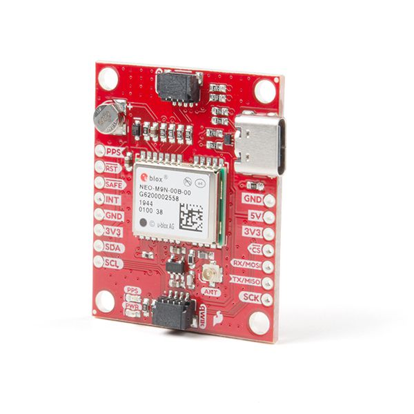
SparkFun GPS Breakout - NEO-M9N, U.FL (Qwiic) High-Quality breakout No Soldering Required Breadboardable Contains a Rechargeable backup battery allowi
The SparkFun NEO-M9N GPS Breakout is a high quality, GPS board with equally impressive configuration options. The NEO-M9N module is a 92-channel u-blox M9 engine GNSS receiver, meaning it can receive signals from the GPS, GLONASS, Galileo, and BeiDou constellations with ~ 1.5 meter accuracy. This breakout supports concurrent reception of four GNSS maximizes position accuracy in challenging conditions increasing precision and decreases lock time and thanks to the onboard rechargeable battery, you'll have backup power enabling the GPS to get a hot lock within seconds! Additionally, this u-blox receiver supports I2C (u-blox calls this Display Data Channel) which made it perfect for the Qwiic compatibility so we don't have to use up our precious UART ports. Utilizing our handy Qwiic system, no soldering is required to connect it to the rest of your system. However, we still have broken out 0.1" -spaced pins in case you prefer to use a breadboard. The NEO-M9N module detects jamming and spoofing events and can reports them to the host, so that the system can react to such events. A SAW (Surface Acoustic Wave) filter combined with an LNA (Low Noise Amplifier) in the RF path is integrated into the NEO-M9N module which allows normal operation even under strong RF interferences. U-blox based GPS products are configurable using the popular, but dense, windows program called u-center. Plenty of different functions can be configured on the NEO-M9N: baud rates, update rates, geofencing, spoofing detection, external interrupts, SBAS/D-GPS, etc. All of this can be done within the SparkFun Arduino Library! The SparkFun NEO-M9N GPS Breakout is also equipped with an on-board rechargeable battery that provides power to the RTC on the NEO-M9N. This reduces the time-to-first fix from a cold start (~24s) to a hot start (~2s). The battery will maintain RTC and GNSS orbit data without being connected to power for plenty of time. Software Configurable Geofencing Odometer Spoofing Detection External Interrupt Pin Control Low Power Mode Many others!
