Trusted shipping
Easy returns
Secure shopping
Buy LCD1602 Character LCD Input/Output Expansion Board Keypad Shield Compatible with Arduino in United States - Cartnear.com
LCD1602 Character LCD Input/Output Expansion Board Keypad Shield Compatible with Arduino
CTNR1579156 CTNR1579156ITCARDIAG
2027-03-20
/itm/lcd1602-character-lcd-inputoutput-expansion-board-keypad-shield-compatible-with-arduino-1579156
USD
11.95
$ 12 $ 12 1% Off
Item Added to Cart
customer
*Product availability is subject to suppliers inventory
SHIPPING ALL OVER UNITED STATES
100% MONEY BACK GUARANTEE
EASY 30 DAYSRETURNS & REFUNDS
24/7 CUSTOMER SUPPORT
TRUSTED AND SAFE WEBSITE
100% SECURE CHECKOUT
| Type | Modules & Embedded Solutions |
|---|
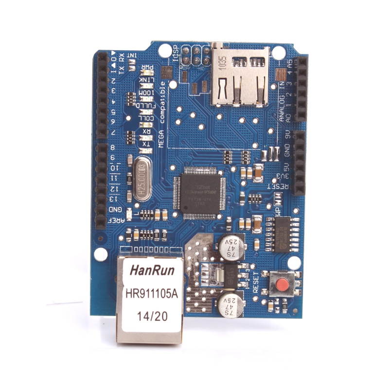
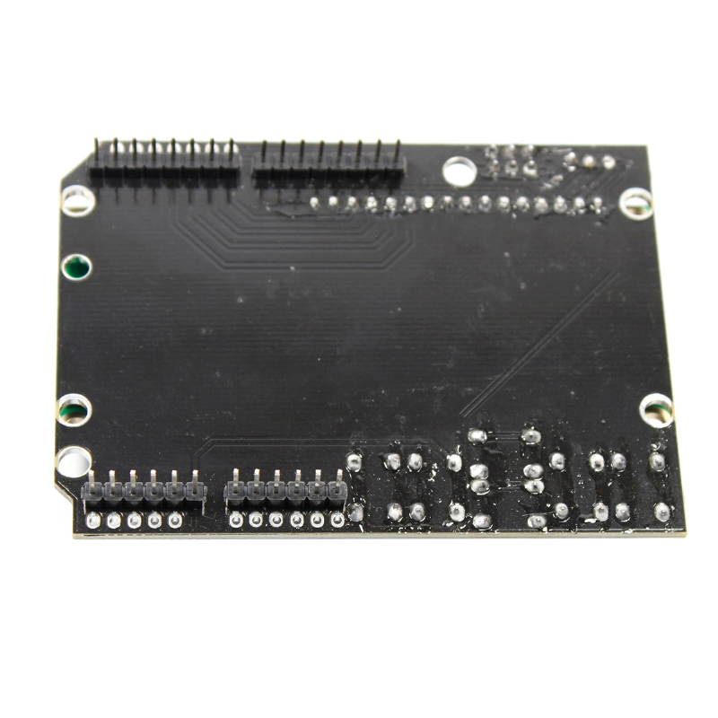
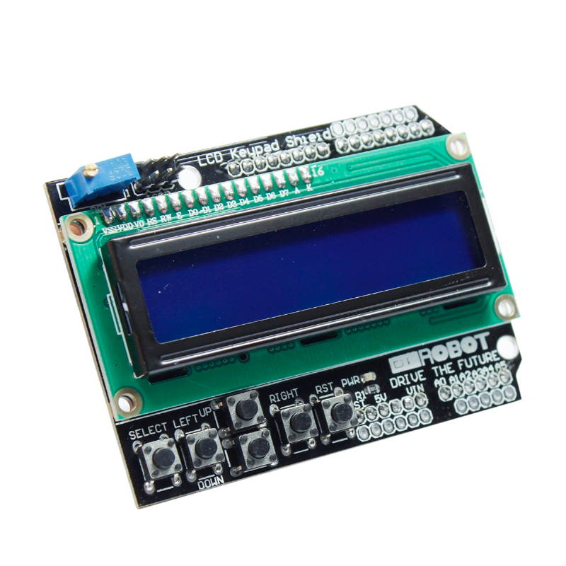
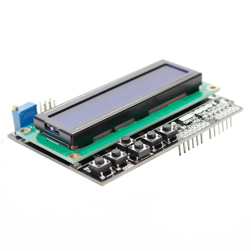
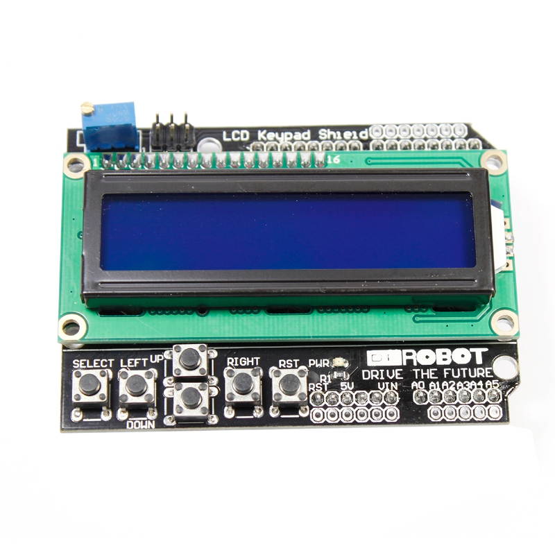
Arduino LCD1602 character LCD expansion board, PCB immersion gold processing, full of materials, the motherboard uses a new high-quality 2 lines 16 characters LCD, not only has contrast adjustment knob, backlight selection switch, also has 4 direction buttons, 1 selection button And a reset button; this 1602 LCD expansion board really simplifies the circuit, directly plug this board into the Arduino Duemilanove controller. Specifications
1.
Module size: 20.5 mm × 41mm
2.
Module weight: 57g Introduction to 1602 Character LCD 1602LCD main technical parameters:
1.
Display capacity: 16 × 2 characters
2.
Chip working voltage: 4.5 - 5.5V
3.
Working current: 2.0 mA ( 5.0V )
4.
Module best working voltage: 5.0V
5.
Character size: 2.95 × 4.35 (W × H) mm 1 VSS power ground 9 D2 data 2 VDD power positive 10 D3 data 3 VL liquid crystal display bias 11 D4 data 4 RS data / command selection 12 D5 data 5 R/W read/write selection 13 D6 data 6 E enable signal 14 D7 data 7 D0 data 15 BLA backlight positive 8 D1 data 16 BLK backlight negative
Pin 1: VSS is the ground power.
Pin 2: VDD is connected to 5V positive power supply.
Pin 3: VL is the contrast adjustment end of the LCD monitor. When the positive power is connected, the contrast is the weakest. The highest, too high contrast will produce "ghosting", you can adjust the contrast through a 10K potentiometer.
Pin 4: RS is the register selection. When the high level is selected, the data register is selected, and when the low level is selected, the instruction register is selected.
Pin 5: R/W is the read/write signal line. When it is high, it performs a read operation, and when it is low, it performs a write operation. When RS When the R/W is low, the command or display address can be written. When RS is low, R/W is high. The busy signal can be read, and data can be written when RS is high and R/W is low.
Pin 6: The E terminal is the enable terminal. When the E terminal changes from a high level to a low level, the liquid crystal module executes the command.
Pins 7 to 14: D0 to D7 are 8-bit bidirectional data lines.
Pin 15: The backlight is positive.
Pin 16: Backlight negative.
Instructions for the 1602LCD: The controller inside the 1602 LCD module has 11 control commands, as shown in the table below: Serial number command RS R/W D7 D6 D5 D4 D3 D2 D1 D0 1 clear screen 0 0 0 0 0 0 0 0 0 1 2 cursor returns 0 0 0 0 0 0 0 0 1 * 3 input mode 0 0 0 0 0 0 0 1 I/D S 4 display on/off control 0 0 0 0 0 0 1 D C B 5 cursor or character shift 0 0 0 0 0 1 S/C R/L * * 6 set function 0 0 0 0 1 DL N F * * 7 character occurrence memory address 0 0 0 1 character occurrence memory address 8 data memory address 0 0 1 display data memory address 9 read busy flag or address 0 1 BF counter address 10 writes to CGRAM or DDRAM) 1 0 data content to be written 11 data content read from CGRAM or DDRAM reading 1 1 1602 LCD module read and write operations, screen and cursor operations are achieved through instruction programming.
(Note: 1 is high level and 0 is low level)
Command 1: Clear display, command code 01H, cursor reset to address 00H position.
Instruction 2: The cursor is reset and the cursor returns to address 00H.
Instruction 3:
1.
Module size: 20.5 mm × 41mm
2.
Module weight: 57g Introduction to 1602 Character LCD 1602LCD main technical parameters:
1.
Display capacity: 16 × 2 characters
2.
Chip working voltage: 4.5 - 5.5V
3.
Working current: 2.0 mA ( 5.0V )
4.
Module best working voltage: 5.0V
5.
Character size: 2.95 × 4.35 (W × H) mm 1 VSS power ground 9 D2 data 2 VDD power positive 10 D3 data 3 VL liquid crystal display bias 11 D4 data 4 RS data / command selection 12 D5 data 5 R/W read/write selection 13 D6 data 6 E enable signal 14 D7 data 7 D0 data 15 BLA backlight positive 8 D1 data 16 BLK backlight negative
Pin 1: VSS is the ground power.
Pin 2: VDD is connected to 5V positive power supply.
Pin 3: VL is the contrast adjustment end of the LCD monitor. When the positive power is connected, the contrast is the weakest. The highest, too high contrast will produce "ghosting", you can adjust the contrast through a 10K potentiometer.
Pin 4: RS is the register selection. When the high level is selected, the data register is selected, and when the low level is selected, the instruction register is selected.
Pin 5: R/W is the read/write signal line. When it is high, it performs a read operation, and when it is low, it performs a write operation. When RS When the R/W is low, the command or display address can be written. When RS is low, R/W is high. The busy signal can be read, and data can be written when RS is high and R/W is low.
Pin 6: The E terminal is the enable terminal. When the E terminal changes from a high level to a low level, the liquid crystal module executes the command.
Pins 7 to 14: D0 to D7 are 8-bit bidirectional data lines.
Pin 15: The backlight is positive.
Pin 16: Backlight negative.
Instructions for the 1602LCD: The controller inside the 1602 LCD module has 11 control commands, as shown in the table below: Serial number command RS R/W D7 D6 D5 D4 D3 D2 D1 D0 1 clear screen 0 0 0 0 0 0 0 0 0 1 2 cursor returns 0 0 0 0 0 0 0 0 1 * 3 input mode 0 0 0 0 0 0 0 1 I/D S 4 display on/off control 0 0 0 0 0 0 1 D C B 5 cursor or character shift 0 0 0 0 0 1 S/C R/L * * 6 set function 0 0 0 0 1 DL N F * * 7 character occurrence memory address 0 0 0 1 character occurrence memory address 8 data memory address 0 0 1 display data memory address 9 read busy flag or address 0 1 BF counter address 10 writes to CGRAM or DDRAM) 1 0 data content to be written 11 data content read from CGRAM or DDRAM reading 1 1 1602 LCD module read and write operations, screen and cursor operations are achieved through instruction programming.
(Note: 1 is high level and 0 is low level)
Command 1: Clear display, command code 01H, cursor reset to address 00H position.
Instruction 2: The cursor is reset and the cursor returns to address 00H.
Instruction 3: